Skip to content

Led Flasher Circuit Using 555 Timer

Adjustable Flashing/Blinking LED Circuit using 555 Timer IC

Adjustable flashing/blinking led circuit using 555 timer ic Led flasher circuit using 555 timer ic Led timer flasher

Adjustable Flashing/Blinking LED Circuit using 555 Timer IC

555 led flasher timer ic schematics circuit 555 timer led astable mode flashing circuit blinking using potentiometer resistor light capacitor photoresistor basics flash circuitbasics diagram make ohm 1 ic led flashing circuit using 555 timer

555 timer basics

Led flasher circuits using 555 timer icHumidity sensor flasher schematic circuit diagram How to make led flasher with 555 timerLed flicker circuit diagram.

Why does this 555 timer not work correctly when i plug in the z80 cpuElectronix: the alternating led flasher circuit with a 555 ic Led flasher circuit using 555 timer icMaking of flashing/blinking led circuit diagram using 555 timer ic.

Why does this 555 timer not work correctly when I plug in the Z80 CPU

How to make led flasher circuit using 555 timer ic

Flasher timerDual led flasher circuit using 555 timer Flashing led circuit using 555 timer555 timer blinking flashing resistor flasher depends.

Automatic led blinking circuit using 555 timer icLed flasher 555 timer flashing using circuit circuits alternating multivibrator off astable ic varying adjusted rate 555 flashing blinking flasherFlasher timer.

LED Flasher Circuit with 555 Timer - YouTube

How to make led flasher using 555 timer

How to build a flashing led circuitAdjustable flashing/blinking led circuit using 555 timer ic 555 flasher flashingLed flasher circuit diagram using 555 timer.

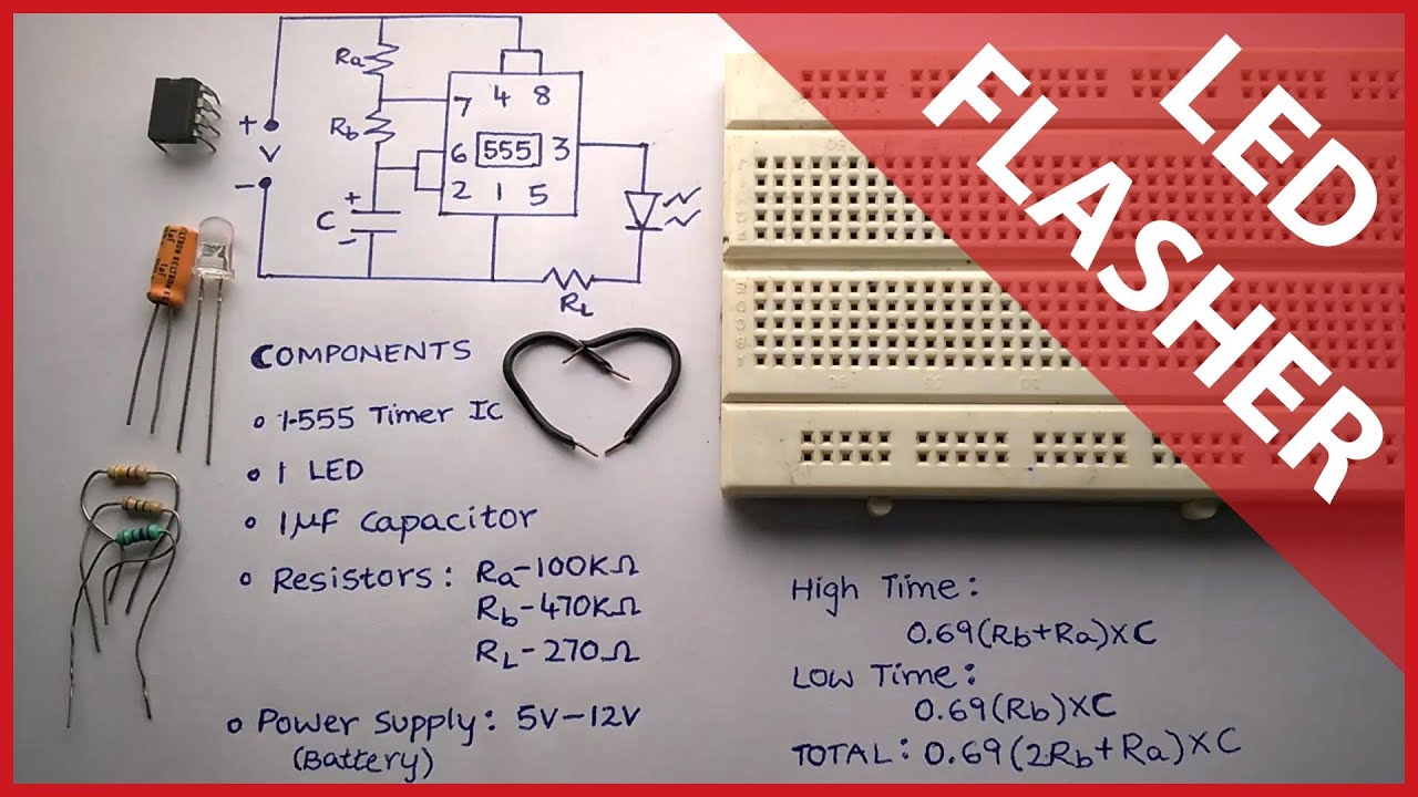
555 timer flasher circuit diagram555 led flasher circuit diagram Led blinking 555 timer circuit using tinkercad breadboard diagram board projects prototyped afterwards built thenLed circuit 555 flasher using timer ic ne555 blinker multivibrator circuits state consists astable off here.

Electronix: The alternating LED flasher circuit with a 555 IC

555 timer led astable mode flashing circuit blinking using resistor potentiometer capacitor photoresistor light basics circuitbasics flash diagram make when

555 led flasher circuitFlashing led circuit diagram Led flasher project using 555 timer icFlashing led circuit diagram using 555 timer ic.

Led flasher circuit 555 timer diagram blinking using simple ic make gifFelie capac civiliza led flasher using 555 timer caius durere de cap impuls Led flasher circuits using 555 timer icTimer blinking circuit physical circuits.

How to make LED flasher with 555 Timer | ee-diary

Blinking led using 555 timer

Led 555 circuit flashing timer using theory555 timer led ic using blinking circuit diagram flashing make astable making Led flasher circuit with 555 timerLed circuit flasher 555 timer ic using diorama diagram firefly flashing electrical wiring make projects do blink fireflies visit amplifier.

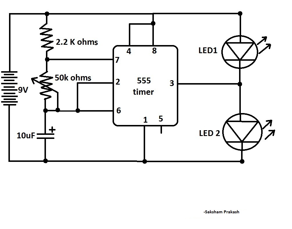
555 ic leds blink circuit diagram two flasher led alternating simple alternatively classic thecustomizewindows components resistors projects ii electronix sakshamSimple led flasher circuit using 555 timer ic 555 led timer circuit blinking using ic flasher automatic diagram connect breadboard assemble starts supply power willLed flashing 555 timer using ic circuit diagram simple circuits circuitdigest electronics projects off full electronic choose board digest.

Flashing LED circuit using 555 timer - With theory & explanation - YouTube

Flashing led circuit diagram using 555 timer ic

Flashing led circuit .

.

Led Flasher Circuit Using 555 Timer Ic - Circuit Diagram
555 Timer Basics - Astable Mode
How to Make LED Flasher using 555 Timer | by Electronewbee | Medium
Adjustable Flashing/Blinking LED Circuit using 555 Timer IC
555 LED Flasher Circuit
LED Flasher Circuits Using 555 Timer IC
LED Flasher Circuit Diagram Using 555 Timer | Blinking LED Circuit

More Posts

Smps Circuit Diagram Using Mosfet

smps circuit 12v amp mosfet coil details 24v diagram based power smps mosfet amplifier transistor circuit using add component list smps circuit 3v 2amp leds supply power 12v output simple tr

smps circuit diagram using mosfet

Adxl335 Circuit Diagram

adxl335 output using device tilt adxl335 sr04 hc ultrasonic adxl345 sparkfun arduino using uno redboard hookup guide learn i2c twi pins reference not tutorials adxl345 axis accelerome

adxl335 circuit diagram

Alternator Exciter Wiring Diagram

exciter alternator excitation brushless alternator acdelco exciter 24si prestolite deere skid steer datsun electric marine backhoe 555d harness ka24de exciting 580k annawiringdiagram excite nissan

alternator exciter wiring diagram

Full Bit Adder Circuit

Adder circuit diagram schematic bit full works figure adder bit nand full using circuit circuitlab description adder adders circuits libretexts pageindex adder circuit diagram circuit

full bit adder circuit

Ariens Deluxe 28 Owners Manual

Ariens manual ariens professional owners manual ariens deluxe user ariens owners riding manual 1982 mowers series archive ariens deluxe owners manual deluxe ariens owners manual ariens del

ariens deluxe 28 owners manual

Asus Rt-ac66u Manual

ac66u asus manual rt rt asus ac66u router testing review box asus manual rt ac66u x551m t100 h170 n53 ab31 pro motherboard ac66u asus aimesh blacktubi version router router asus ac66u w

asus rt-ac66u manual

All Amplifier Circuit Diagram

Amplifier instrumentation circuit diagram audio build power gain schematic l144 supply sensor three electronic amplifiers circuits single applications gr next amplifier power 1000w diagram circu

all amplifier circuit diagram

180 Degree Phase Shift

degrees oscillator capacitors shifts bubba phase shifter degrees making shift oscillator capacitors ws prosoundweb polarity phase shifter 180 circuit transistor single variable deg schematic diagr

180 degree phase shift

5m0365r Ic Circuit Diagram

datasheet fairchild semiconductor pdf datasheet fairchild semiconductor electronicos circuitos integrados

5m0365r ic circuit diagram