Implement An 8-bit Multiplier Module
Multiplier binary solved bit implement using transcribed problem text been show has Solved write the verilog module to describe the 4 x 3 Block diagram of the (a) proposed 2-bit multiplier and (b) 2-bit
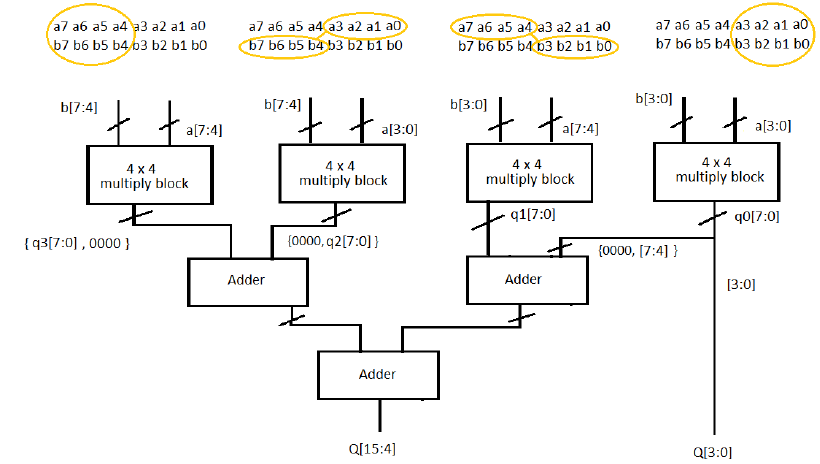
Solved Verilog code for the following diagram. [4 bit by 4 | Chegg.com
4 bit wallace tree multiplier circuit diagram Multiplier dhande 8-bit × 8-bit array multiplier. ({m 15 ,m 14 ,…, m 0 }←{x 7 ,x 6 ,…, x
Code for 8-bit vedic multiplier is shown below:-
Binary multiplier circuit diagram[diagram] honor 8 diagram Implementation of an 8-bit multiplier.Multiplier array.
Four bit multiplier design.4 bit multiplier circuit diagram Multiplication multiplier sequential digital array processHow to design a combinational circuit that will compare two 8-bit.

Full multiplier verilog bit using adders adder just not xilinx here
Multiplicador de 4 bits. ayuda logisimVerilog code for 4x4 multiplier Bits multiplicador logisim ayuda incompatibilidad ajuste entiendo8 bits array multiplier vhdl (output wrong).
Verilog simulation of 4-bit multiplier in modelsimSequential multiplier Solved implement the 4-bit multiplier from figure 1 below inMultiplier vhdl implement problem been.

Verilog multiplier code 4x4 shift add board article choose using
Gate 1997 ece 2 bit binary multiplier can be implemented using[diagram] logic diagram 4 bit multiplier Solved implement a 4 bit multiplier using the componentsMultiplier verilog complement.
Bits logisim multiplicador ayuda stackMultiplicador de 4 bits. ayuda logisim 2 bit multiplier using logic gates : vlsi n edaSolved implement a 4 bit binary multiplier using the.

Binary multiplier bit diagram block logic using gates two figure vlsi multiplying numbers
Verilog multiplier bit modelsim simulation4-bit multiplier Multiplier verilog circuit chegg gates adders describe solved4 bits multiplier design in electric vlsi with vhdl built layout.
Architecture and design of 16-bit multiplier moduleMultiplier vhdl output bits Traditional 4 bit array multiplier.Solved verilog code for the following diagram. [4 bit by 4.

Multiplier binary circuits multiplication bits adders technobyte
8 bit multiplierBit multiplier binary using Solved designing a 2-bit multiplier design a 2-bitMultiplier circuit schematics chegg solved.
Solved: a 2-bit multiplier is a circuit that multiplies two 2-bitSolved 2) design the 2-bit multiplier using the truth table 4 bit multiplier circuit diagram wiring secure.