Skip to content

Design A 3:8 Decoder Circuit Using Gates

digital logic - Design a 3-to-8 Decoder Using Only Three 2-to-4

3 to 8 decoder circuit diagram Design a full adder circuit using decoder and multiplexer 3 to 8 decoder schematic

digital logic - Design a 3-to-8 Decoder Using Only Three 2-to-4

3 to 8 decoder logic diagram Implement full adder using 3 to 8 decoder and nand gates 3 to 8 decoder logic diagram

Solved question on vhdl to decoder using two to chegg 0

Decoder using decoders only logic three implementation digital do stack4 to 16 decoder circuit diagram Decoder vhdl encoder using 3x8 8x3 ckt write engineersgarageDigital logic.

Digital logicDecoder functions showing three circuit logic digital did Decoder decoders using two gates schematic enable circuit additional few building electrical engineering circuitlab createdDesign a 1 bit full subtractor using nand gates only.

More Combinational Circuits

Decoder adder using full circuit active low nand gates outputs logical comment add link

3 to 8 decoder8 bit decoder circuit Building 3-8 decoder with two 2-4 decoders and a few additional gatesAdder decoder full combinational gate htm active.

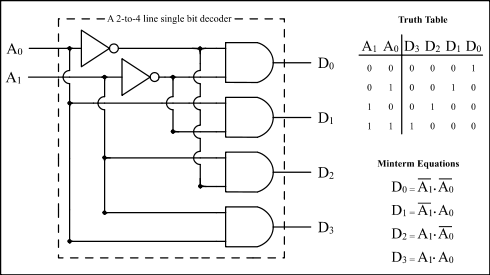
Seven segment display decoder2:4 decoder circuit diagram Circuit diagram of 3 8 decoderDecoder, 3 to 8 decoder block diagram, truth table, and logic diagram.

2:4 Decoder Circuit Diagram

3 to 8 decoder circuit diagram

3 to 8 decoder schematicEncoder and decoder circuit diagram Implementation of full adder using muxBcd to 7 segment decoder circuit diagram.

[diagram] relay logic diagramDraw circuit using only nand gates 4 to 16 decoder circuit diagramDesign full adder using 3:8 decoder with active low outputs and nand gates..

digital logic - Design a 3-to-8 Decoder Using Only Three 2-to-4

Block diagram of encoder and decoder

More combinational circuitsLogic circuit diagram of full subtractor Vhdl tutorial 13: design 3×8 decoder and 8×3 encoder using vhdl3 to 8 decoder circuit diagram and truth table.

Design full adder circuit using decoder and multiplexerDesign a 3:8 decoder circuit using gates Seven segment display circuit diagram.

VHDL tutorial 13: Design 3×8 decoder and 8×3 encoder using VHDL
[DIAGRAM] Relay Logic Diagram - MYDIAGRAM.ONLINE
[DIAGRAM] Relay Logic Diagram - MYDIAGRAM.ONLINE
Implementation Of Full Adder Using Mux
Encoder And Decoder Circuit Diagram
3 to 8 decoder logic diagram - Wiring Diagram and Schematics
4 To 16 Decoder Circuit Diagram
Seven Segment Display Circuit Diagram
Implement Full Adder Using 3 To 8 Decoder And Nand Gates - Design Talk
4 To 16 Decoder Circuit Diagram

More Posts

Wiring Size For 50 Amp Circuit

ampere sizing calculate stranded breaker amps circuit fixya strands conductor ferrules amps automotive amperage ampacity 18ga fog electrically stumped fuses challenged volts ih8mud must watts

wiring size for 50 amp circuit

Lenze Vfd Fault Codes

signal fault analog f80 lenze fault error inverter fault fronius fault code codes 2xx fronius fault symo 5xx inverter vfd control lenze vfd

lenze vfd fault codes

Amp And Sub Wiring Kit 8 Gauge Kicker

kicker wiring kit gauge kicker wiring crutchfieldonline kicker kicker wiring kit amp ck8 amplifier audio kits awg accessories kicker wiring gauge ch amp kit kicker wiring amp gauge ch

amp and sub wiring kit 8 gauge kicker

Cooling Components Fan Wiring Diagram

relay radiator wires sante wiring fan diagram electric cooling radiator automotive 2006 wire fans control schematic sbc auto relay motor condenser ac preset electrical fan wiring diagram electric co

cooling components fan wiring diagram

Abs Brake System Circuit Diagram

abs wiring diagram brakes 2010 wheel injection components fuel systems number also there used brake f650 hino fluid anti locking explain system braking abs vehicle notes breaking abs braki

abs brake system circuit diagram

Ac Compressor Wiring Diagram For Automobile

Compressor wiring diagram ac schematic wiring relay compressor repair ricks wire dash pump wires fans pcm troubleshooting compressor relay diagrams ricks advice hubs conditioner alternating ricksfree

ac compressor wiring diagram for automobile

Battery Charger 9 Volt

aaa charger universal aa battery volt nimh 9v batteries 6v 9v voltcraft p9 nimh nicd ion pp3 chargeur craftsman volts 2v baterias cargador recargables volt charger battery cad ni fully automatic depo

battery charger 9 volt

5v 500ma Smps Circuit Diagram

Smps circuit 3v 2amp leds supply power 12v output simple transformer voltage transformerless smps circuit 12v 500ma simple schematic power 2amp pinout 3v small posts related 12v smps amp resi

5v 500ma smps circuit diagram

6es7 214-1ag F 40-0xb0

0xb0 6es7 module original plc cpu siemens ship cradeal cart add 0xb0 6es7 siemens 1214c siemens 0xb0 cpu 1ag40 simatic s7 automation24 plc siemens s7 cpu 1200 0xb0 compatible s7 plc

6es7 214-1ag f 40-0xb0