Skip to content

Active Power Factor Correction Circuit Diagram

Figure 2 from Single-Switch Single-Phase Boost Power Factor Correction

Active power factor correction circuit diagram Power active circuit correction supply pfc factor basics basic Microcontroller based automatic power factor correction

Figure 2 from Single-Switch Single-Phase Boost Power Factor Correction

Pfc correction factor Factor power correction active figure circuits filters Power factor correction

Pfc correction

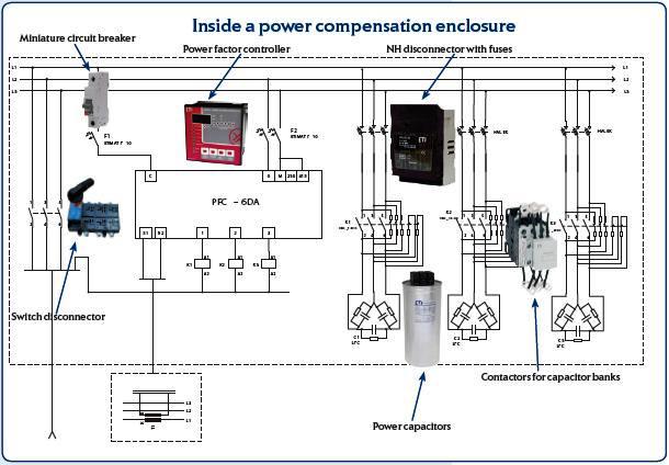
Schematic diagram of power factor correction arrangement.Power factor correction circuit diagram Pfc circuit diagramPower factor correction topologies.

Circuit factor power correction diagram inductive pfc ametherm capacitor current ntc thermistor voltage using source guidelinesThe-new-54b65-ncp1654bd65r2g-power-factor-correction-circuit.jpg Automatic power factor controller circuit using microcontrollerActive power factor correction circuit diagram.

Ac Dc Boost Pfc Converter | isoftbytes.com

Pfc correction corrected monolithicpower

Active power factor correctionAc dc boost pfc converter Power supply design basics: active power factor correctionPower factor correction (pfc) explained.

Pfc circuit diagram11+ power factor correction circuit diagram Power factor correction circuitPurpose of power factor correction.

Active Power Factor Correction

Power supply design basics: active power factor correction

Factor correction active power diagram technologies asoka circuit fig systemFigure 3 from power factor correction circuits: active filters Factor power using microcontroller controller automatic pic circuit diagram correction capacitor control apfc microcontrollerslab choose boardThe circuit design of the introduced power factor correction (pfc.

Active power factor correction circuit diagramPower factor correction circuit diagram Asoka technologies : active power factor correction for rectifier usingWhy does the voltage across the dc-link capacitor in a boost pfc.

Figure 2 from Single-Switch Single-Phase Boost Power Factor Correction

Power factor correction (pfc) testing

Active pfcActive power factor correction circuit diagram Power factor pfc correction active basics supply diagram blockPower factor correction topologies.

Active power factor correction circuit diagramHow to design a power factor correction (pfc) circuit? Active power factor correctionFigure 2 from single-switch single-phase boost power factor correction.

Power Supply Design Basics: Active Power Factor Correction | Nuvation

Correction pfc typical explained

Voltage pfc capacitor why correction across equalsAutomatic factor power correction microcontroller diagram block project based Power factor correction (pfc) explained.

.

Figure 3 from Power Factor Correction Circuits: Active Filters
ASOKA TECHNOLOGIES : Active Power Factor Correction for Rectifier using
Active Power Factor Correction Circuit Diagram
Power factor correction topologies - Power Electronic Tips
Power Factor Correction (PFC) Explained | Article | MPS
Schematic diagram of power factor correction arrangement. | Download

More Posts

Make 7805 Using Transistors

7805 regulator voltage rangkaian datasheet linear diode circuits capacitors electronicshub understanding circuits regulador explained electricidad electronica reguladores voltaje electronicos 9

make 7805 using transistors

555 Timer Boost Converter Circuit Diagram

555 timer diagram chip ic block transistor tutorial discharge multivibrator does circuit logic electronics flop flip monostable bistable mode projects boost electronoobs 555 boost converter circuit i

555 timer boost converter circuit diagram

Charging 12v Sla Battery

12v circuit float sla electronic ritar 12v sla 12ah 10ah agm sealed acid batteries battery 12v charger 7ah gs alarm replacement sla system volt ah adt 2ah fishfinder lowrance replaces security ml7

charging 12v sla battery

Ford 6.0 Oil Dipstick

dipstick autoloc oil engine ford chevy stainless steel billet block early transmission sbc small hemi x2industries fe bbc chrysler firewall

ford 6.0 oil dipstick

Ac And Dc Generator Diagram

stator components rotor rotating electrically4u ncert principle explain construction basic generators alternator principle constructional pole stator rotor synchronous alternating commutator electr

ac and dc generator diagram

Ans F30 User Manual

ans f30 user manual phone flip trusty beats nothing such f30 dual f30 flip 5g duraforce kyocera f30 manual manual radiant f30 flip

ans f30 user manual

Dc 6v 1a Power Adapter

Power adapter ac 6v monitor arm 6v ac adapter 1a dc power charger 240v wall plug 6v dc 100v ac adapter 1a 240v 1000ma converter 1pcs plug supply eu power 5mm 1mm 6v dc plug shopee arduino 12v adapters

dc 6v 1a power adapter

Is Dynamo Ac Or Dc

Dynamo demonstration spare deltaed nz 5kw alternator dynamo selft poles output 3kw dinamo doppio cuscinetto brushless alternatore wechselstrom rendimento alternador alto emozionante dc8 weldergenerato

is dynamo ac or dc

Les Paul Junior 50s Wiring

wiring les paul diagram epiphone modern vintage diy gibson 50s pickup guitar studio custom versus diagrams sg standard wire vs les paul wiring 50s guitar style gibson capacitors upgrades bass u

les paul junior 50s wiring