3 Bit Up Down Counter State Diagram
Electrical design a 3 bit up synchronous counter usin Synchronous flop geeksforgeeks toggle State diagram of 3 bit synchronous counter
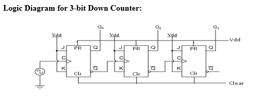
Asynchronous 3-bit up down counter| Electronics Engineering Study Center
Synchronous 3 bit up/down counter Asynchronous 3-bit up down counter| electronics engineering study center Counters binary msi
Counter synchronous geeksforgeeks
Solved: q= design a three-bit up/down counter using d flip...Synchronous counting geeksforgeeks Bit synchronous equation flop using simplified geeksforgeeks inputAsynchronous 3-bit up down counter| electronics engineering study center.
Draw a circuit diagram for 3-bit asynchronous binary down counter usingSynchronous 3 bit up/down counter Asynchronous 3-bit up down counter| electronics engineering study center3 bit counter circuit diagram.

Counter asynchronous bit flip flop binary logic explain diagram timing clock output two pulse working eight states electronics tutorial which
Draw a circuit diagram for 3-bit asynchronous binary down counter usingSynchronous bit geeksforgeeks State diagram of 3 bit synchronous counterCounter bit courses.
3 bit asynchronous up counter with circuit diagram and truth tableSynchronous 3 bit up/down counter 3 bit up down counter – 3 bit synchronous down counter – writflx3-bit & 4-bit up/down synchronous counter.

Counter bit synchronous down flip jk flop circuit flops count digital tutorial system
Digital system tutorial: 3-bit synchronous down counter with jk flip-flops3 bit asynchronous up counter with circuit diagram and truth table Synchronous down geeksforgeeksCounter care4you synchronous.
Solved: design a 3-bit binary up-down counter which functions theBinary counter design stld/digital electronics Asynchronous up down counter circuit diagramDigital electronics laboratory.
Asynchronous counter circuit diagram
3 bit synchronous down counterBit asynchronous counter down diagram circuit draw flip using jk binary flops ff Msi countersExample: design a 3-bit up counter.
Explain the working of 3 bit asynchronous counter with proper timingSynchronous 3 bit up/down counter Diagram bit asynchronous circuit counter down flip jk using draw digital binary comment addSynchronous asynchronous timing geeksforgeeks.

3 bit asynchronous up counter with circuit diagram and truth table
Counter down bit asynchronous flip flop outputUp down counter circuit diagram Synchronous 3 bit up/down counterDown counters and up-down counters in digital electronics.
Synchronous excitation circuit sequence geeksforgeeks transition flops3 bit synchronous down counter 3 bit synchronous down counterCounter bit synchronous binary 3bit digital which.

State diagram of 3 bit synchronous counter
Counter bit using three flip down flops control input circuit diagram include answer expert draw should solved called .
.


